


AC Drive inverter wiring
1. Main circuit wiring
The inverter main circuit terminals shown as below Figure.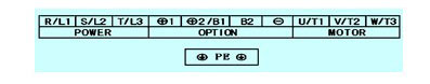
(1) DC reactor connection terminals (φ1, φ2/b1)
DC reactor connection terminals connect to the DC reactor to improve power factor with a short-circuit conductor connected to the terminals, when using the DC reactor, remove the short-circuit conductor first.
Note: Do NOT need to remove the conductor if the DC reactor is not connected.
(2) The variable frequency drive three phase AC input terminals (r/l1, s/l2, t/l3)
The power line's input terminals connect to 3 phase AC power through line protection or leakage protection breaker, it does not need to consider the connection of phase sequence. What needs to pay attention is the three-phase AC power must NOT be connected to the frequency inverter output terminals directly, otherwise it will lead to the inverter's internal components damaged.
(3) Ground terminal (PE)
The AC drive will generate leakage current, the higher the carrier frequency, the larger the leakage current. The leakage current of the whole ac drive is more than 3.5ma, the leakage current size is determined by the service conditions, in order to ensure safety, the variable frequency inverter and electric AC motor must be grounded.
(4) DC power input terminals (φ1, θ)
The DC input terminals of the external brake unit are the positive and negative terminals of the DC bus.
(5) Brake unit connection terminals (φ2/b1, b2)
Generally small power ac drive (0.75 ~ 15kw) built-in braking resistor, while the 18.5kw and above need external braking resistor connection.
(6) The inverter 3-phase AC output terminal (C)
The electric motor should be connected to the output terminals by correct phase sequence, if the motor is in the reverse direction, then change any two phase of (u/t1, v/t2, w/t3), it also can be achieved by setting the variable speed drive parameters. It should be noted that the output terminal can not connect the phase capacitor and surge absorber.
2. Control circuit terminals wiring
(1) The cable shielding
The frequency inverter cable shielding can adopt grounded metal tube or shielded cable. One end of Shielded layer connects to the variable frequency drive control circuit common (COM), but do not connect to the ac drive ground end (e), the other end of the shield is vacant.
(2) Control circuit grounding
- the weak voltage/current loop wire connect to earth, and the grounding wire should not be used as the transmitted signal circuit;
- the wire's grounding should be in the AC drive inverter side, use a dedicated ground terminal and do not shared with other ground terminals.
(3) The control line and the main circuit cable laying
The frequency inverter control lines should be laid separate from the main circuit cable and other power cable, and as far away as possible from the main circuit like more than 100mm; And don't parallel to the main circuit cable laying, do not cross the main circuit, if it must cross then it should be a vertical cross method.
(4) As the low voltage ac drive over-current of the control circuit cables is generally small, so the size of the control cable can be standardized, in order to avoid the interference caused by malfunction, the control cables should be twisted shielded wires.
(5) The volume control switching line
The variable speed drive switching control lines are allowed not to use the shielded wire, but two of the same signal lines must be twisted around each other, the twist pitch of the strands should be as small as possible, and the shielded layer connects to the ground terminal E of the frequency inverter, the signal cable maximum length should not exceed 50m.
3. Precautions
(1) Multiple variable frequency drives ground should be connected to the earth respectively, do not make the ground wire form a loop;
(2) The grounding resistance should be less than 10 ω. The grounding cable diameter should be determined by the ac drive power;
(3) If the supply line is zero/earth wire shared, it is better to consider a separate laying for the earth wire;
(4) Never share grounding wire with the welding machines and other power equipment.


